-40%
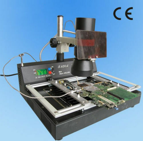
NEW T870A BGA IRDA Iron Welder Infrared Heating Rework Soldering Station s
$ 256.08
- Description
- Size Guide
Description
T870A┬ĀIRDA┬ĀWelder┬ĀInfrared┬ĀRework┬ĀStationFeatures:
1.┬ĀAdopt┬Āinfrared┬Āweld┬Ātechnology┬Āwhich┬Āindependent┬Āexploration.
2.┬ĀUse┬Āinfrared┬Āheat,easy┬Āto┬Ācut┬Āthrough,heat┬Āproportion┬Āpiercing┬Ātradition┬Āweld┬Āmachine┬Āwith┬Āsirocco.
3.┬ĀEasily┬Āoperate.Just┬Āneed┬Āone┬Āday┬Ātraining.Can┬Āoperation┬Āthis┬Āmachine.
4.┬ĀDon't┬Āneed┬Āweld┬Ātools.This┬Āmachine┬Ācan┬Āweld┬Āall┬Āthe┬Ācomponent┬Āof┬Ā35x35-50x50mm.
5.┬ĀThis┬Āmachine┬Āhas┬Ā800W┬Āheating┬Āsystem.widely┬Āto240x180mm.
6.┬ĀInfrared┬Āheating┬Ādon't┬Āhave┬Āsirocco┬Āflow.┬ĀDon't┬Āimpact┬Āperimeter┬Āsmall┬Ācomponent.Can┬Āsuitable┬Āfor┬Āall┬Āof┬Āthe┬Ācomponent,especially┬ĀMicro┬ĀBGA┬Ācomponent.
7.┬ĀDefinitely┬Ācan┬Āsatisfy┬Āthe┬Ācomputer,┬Āthe┬Ānotebook,┬Āthe┬Āelectricity┬Āswims┬Āand┬Āso┬Āon┬Āthe┬ĀBGA┬Āsealing┬Āoff/repairs┬Āto┬Ārequest
’╝ø
Specially┬Āespecially┬Āsuits┬Āto┬Āthe┬Ācomputer┬Ānorth┬Āand┬Āsouth┬Ābridge.
Technic┬Āparameter:
Work┬Āfloor┬Āsize
360X240mm
Rated┬Āvoltage┬Āand┬Āfrequency
AC220-230v┬Ā60/50Hz
Complete┬Āmachine┬Āpower
1000W
Infra-red┬Ālamp┬Ābody┬Āpower
150W
Preheating┬Āchassis┬Āpower
800W
Infra-red┬Ālamp┬Ābody┬Āheating┬Āsize
╬”70mm(50x50mm)
Preheating┬Āchassis┬Āpreheating┬Āsize
240x180mm
Infra-red┬Ālamp┬Ābody┬Ātemperature┬Āadjustable
200Ōäā-350Ōäā
Preheating┬Āchassis┬Ātemperature┬Āadjustable
60Ōäā-200Ōäā
Instrument┬Āinventory:
Welding┬Ātable┬Āmain┬Ābody
1
Infra-red┬Ālamp┬Ābody
1
Temperature┬Āsensor
1
Board┬Āsupport┬Āof┬Āthe┬Ācircuit
1
Power┬Āline
1
user's┬Āmanual
’╝ł
Compact┬Ādisc
’╝ē
1
1.┬ĀInspect┬Āthe┬Āmachine┬Āand┬Āthen┬Āopen┬Āit
(
1)┬ĀCheck┬Āif┬Āthe┬Āconnection┬Āwire┬Āof┬Āthe┬Ālamp┬Ābody,┬Āthe┬ĀTemp-sensor┬Āand┬Āpower┬Ācable┬Āis┬Āok.
(2)┬ĀTurn┬Āon┬Āthe┬Āpower┬Āswitch.┬ĀAllow┬Āthe┬ĀT-870A┬ĀPower-On-Self-Test┬Ā(POST)┬Āto┬Ācomplete.┬ĀAfter┬Āthis,┬ĀTemperature┬Āset-points┬Āwill┬Ādisplay┬Ālast┬Āvalue┬Āused.
(3)┬ĀThe┬Āfront┬Āpanel┬Āhas┬Ātwo┬Āswitches,┬Ācontrols┬Āthe┬Āpreheating┬Ādish┬Āand┬Āthe┬Āinfra-red┬Ālamp┬Ābody┬Āseparately;
2.┬ĀPC┬ĀBoard┬ĀComponent┬ĀRemoval┬Āand┬ĀReplacement
(
1)┬ĀPlaced┬Āthe┬ĀPCB┬ĀBoard
Put┬Āthe┬ĀPCB┬Āboard┬Āon┬Āthe┬ĀŌĆ£PCB┬Āboard┬ĀholderŌĆØ,┬Ārotate┬Āthe┬ĀŌĆ£holder┬Āfasten┬ĀnutŌĆØ,┬Āfasten┬Āit.┬ĀMove┬Āthe┬ĀŌĆ£PCB┬Āboard┬ĀholderŌĆØ┬Āto┬Āchoose┬Āthe┬Āright┬Āposition.
(2)the┬ĀProcess┬Āof┬Āunsoldering┬Āand┬Ārepairing
ŌæĀAdjust┬Āthe┬Āposition┬Āof┬Āthe┬ĀPCB┬Āboard,┬Āmake┬Āthe┬Āchip┬Āat┬Āthe┬Ācentre┬Āof┬Āthe┬Ālamp┬Ālight.┬ĀAdjust┬Āthe┬Āheight┬Āof┬Āthe┬Ālamp┬Ābody,┬Ākeep┬Āthe┬Ālamp┬Ā20-30mm┬Āfrom┬Āthe┬Āchip.
ŌæĪPut┬Āthe┬Ātemp-sensor┬Āat┬Āthe┬Āedge┬Āof┬Āthe┬Āchip,┬Ālay┬Āa┬Ābed┬Āof┬Āsolder┬Āflux┬Āaround┬Āthe┬Āchip┬Āand┬Āon┬Āthe┬Ātemp-sensor,┬Āit┬Āwill┬Āmake┬Āthe┬Āmeasured┬Ātemperature┬Āmore┬Āaccurately,┬Āat┬Āthe┬Āsame┬Ātime┬Āthe┬Āsolder┬Āflux┬Āwill┬Āmake┬Āthe┬Āsoldering┬Āchip┬Āmore┬Āperfect,┬Āand┬Ākeep┬Āthe┬Ābonding┬Āpad┬Āaway┬Āfrom┬Āconglutinating┬Āand┬Āhaving┬Ātin┬Āwool.
ŌæóAccording┬Āto┬Āthe┬Āproducing┬Ātechnological┬Ārequirement┬Āor┬Āthe┬Āsize┬Āof┬ĀPCB┬Āboard,┬Āadjust┬Āthe┬Āpre-heat┬Ādish┬Ātemperature(adjustable┬Ā60-200Ōäā).
When┬Āthere┬Āis┬Āwaterproof┬Āsolid┬Āsealing┬Ācompound┬Āon┬Āthe┬Āchip,┬Āplease┬Āopen┬Āthe┬Āpre-heat┬Ādish┬Āto┬Āpulverize┬Āthe┬Āsolid┬Āsealing┬Ācompound┬Āfirst,┬Āthen┬Āclean┬Āit┬Āup.┬ĀYou┬Āmay┬Āadopt┬Āother┬Āmethod┬Āas┬Āsol/hydrosol.┬ĀWhen┬Āyou┬Āadopt┬Āthe┬Āmethod┬Āwe┬Āsupplied,┬Āyou┬Āhad┬Ābetter┬Āchoose┬Āthe┬Ātemperature┬Ābetween┬Ā100Ōäā┬Āand┬Ā140Ōäāaccording┬Āto┬Āthe┬Āproducing┬Ātechnological┬Ārequirement┬Āor┬Āthe┬Āsize┬Āof┬ĀPCB┬Āboard,┬Ācontrol┬Āthe┬Āpre-heat┬Ātime┬Ā3-5┬Āminutes(the┬Ātemperature┬Āwill┬Ābe┬Āsteady)┬Āor┬Ālonger.
Otherwise┬Āif┬Āthe┬Āchip┬Āis┬Āwithout┬Āwaterproof┬Āsolid┬Āsealing┬Ācompound┬Āor┬Āthe┬ĀPCB┬Āboard┬Āis┬Āsmall,┬Āthen┬Āit┬ĀwonŌĆÖt┬Ātransmutation,┬Āwe┬ĀneednŌĆÖt┬Āopen┬Āthe┬Āpre-heat┬Ādish
ŌæŻAccording┬Āto┬Āthe┬Āproducing┬Ātechnological┬Ārequirement┬Āor┬Āthe┬Āsize┬Āof┬Āchip,┬Āchoose┬Āthe┬Āsuitable┬Ātemperature┬Āof┬Āthe┬ĀIR-lamp.
ŌæżUsually,┬Āwhen┬Āthe┬Āchip┬Āsize┬Āis┬Āless┬Āthan┬Ā20*20mm,┬Āwe┬Āadjust┬Āthe┬ĀIR-lamp┬Ātemperature┬Ā220-240Ōäā,┬Āand┬Āif┬Āthe┬Āchip┬Āis┬Āwithout┬Āwaterproof┬Āsolid┬Āsealing┬Ācompound┬Āor┬Āthe┬ĀPCB┬Āboard┬Āis┬Āsmall,┬Āthen┬Āit┬ĀwonŌĆÖt┬Ātransmutation,┬Āwe┬ĀneednŌĆÖt┬Āopen┬Āthe┬Āpre-heat┬Ādish.┬ĀOtherwise,┬Āwe┬Āshould┬Āadjust┬Āthe┬Āpre-heat┬Ātemperature┬Āto┬Ā100-120Ōäā.
When┬Āthe┬Āchip┬Āis┬Ālager┬Āthan┬Ā30*30mm,we┬Āshould┬Āadjust┬Āthe┬Āpre-heat┬Ātemperature┬Āto┬Ā120-140Ōäā┬Āfirst,┬Āwait┬Ā3-5minutes┬Āand┬Āthe┬Ātemperature┬Āwill┬Ābe┬Āsteady.┬ĀThen┬Āadjust┬Ā┬Āthe┬ĀIR-lamp┬Ātemperature┬Āto┬Ā240-260Ōäā,┬Āwe┬Āwill┬Ācomplete┬Āthe┬Āunsoldering┬Āand┬Ārepairing┬Āprocess┬Āconveniently.┬ĀAttention:┬ĀAt┬Āthe┬Ātime,┬Āthe┬Ālight┬Āis┬Āstrong,┬Āthe┬Ātemperature┬Ārises┬Āquickly,┬Āwe┬Āshould┬Āpay┬Āour┬Āattention┬Āon┬Ācontrolling,┬Āavoid┬Āthe┬ĀTemp-sensor┬Ādisplacement,┬Āreflect┬Āon┬Āthe┬Ātemperature┬Āmeasuring.┬ĀWe┬Āshould┬Āalso┬Āpay┬Āour┬Āattention┬Āon┬Ātime┬Ācontrolling,┬Āavoid┬Āburning┬Āout┬Āthe┬Āchip.
ŌæźWhen┬Āachieving┬Āthe┬Āset-up┬Ālamp┬Ātemperature,┬ĀOnce┬Āthe┬Āsolder┬Āliquefied┬Āand┬Āmelted,┬Āuse┬Ātweezers┬Āto┬Āremove┬Āthe┬Āchip.
3.the┬ĀProcess┬Āof┬ĀSoldering┬Āa┬Āchip
It┬Āis┬Āgenerally┬Āthe┬Āsame┬Āas┬Āthe┬ĀŌĆ£(2)Process┬Āof┬Āunsoldering┬Āand┬ĀrepairingŌĆØ,┬Ābut┬Āyou┬Āshould┬Ādo┬Āas┬Āfollows:
ŌæĀClean┬Āthe┬Ātarget┬Āpad┬Āwith┬Āthe┬Ābrush
ŌæĪThen┬Āput┬Āthe┬Āsolder┬Āball┬Āand┬Āa┬Āflat┬Āof┬Āsolder┬Āflux┬Āand┬Āthe┬Āchip┬Āon┬Āthe┬Ātarget┬Āpad
Ōæó┬ĀTurn┬Āon┬Āthe┬Āswitch┬Āof┬Āthe┬Āpre-heat┬Ādish,┬Āand┬Āset-up┬Āthe┬Ātemperature
ŌæŻTurn┬Āon┬Āthe┬Āswitch┬Āof┬Āthe┬ĀIR-Lamp,┬ĀRegulate┬Āthe┬Ātemperature┬Ā(the┬Ātemperature┬Āmust┬Ābe┬Āwarm┬Āenough┬Āto┬Āliquefied┬Āthe┬Āsolder),┬Āfocus┬Āthe┬ĀInfrared┬Ālight┬Āon┬Āthe┬Āchip┬Āto┬Ābe┬Āsolder
Ōæż┬ĀWait┬Āto┬Āallow┬Āthe┬ĀInfrared┬Ālamp┬Āto┬Āheat┬Āthe┬Āsolder┬Āflux┬Āto┬Āwork┬Āas┬Āthe┬Āsolder┬Āballs┬Āon┬Āthe┬Ātarget┬Āchip┬Āpad┬Āreaches┬Āliquid┬Ātemperature.┬ĀUse┬Ātweezers┬Āor┬Āa┬Āvacuum┬Ādevice┬Āto┬Āplace┬Āthe┬Āchip┬Ātarget┬Āposition.┬ĀOnce┬Āthe┬Āsolder┬Āliquefies,┬Āthe┬Āchip┬Āwill┬Ābe┬Āsold┬Āautomatically.
After┬Ācooling┬Āthe┬Āchip,┬Āpick┬Āup┬Āthe┬ĀPCB┬Āboard,┬Ācheck┬Āif┬Āit┬Āis┬Āok.┬ĀIf┬Ānot,┬Āre-operate.
Suggestion:
About┬Āthe┬Ācomponents┬Āwithout┬Āplumbum,┬Āyou┬Āshould┬Āadd┬Ā20-30Ōäā.
4.┬Āthe┬ĀProcess┬Āof┬Āsoldering┬Ākinds┬Āof┬ĀPlug┬Ā(as:┬ĀGAP┬Āplatoon┬Āexpansion┬Āslot┬Āplug┬Āof┬Āthe┬Ācomputer┬Āmotherboard)
Usually┬Āwe┬Ācover┬Āthe┬Āhardware┬Āand┬Āthe┬ĀPCB┬Āboard┬Ā(which┬ĀwonŌĆÖt┬Ābe┬Āmaintained)┬Āwith┬Āthe┬Āaluminium-foil┬Āpaper,┬ĀThen┬Āput┬Āthe┬ĀPCB┬Āboard┬Āon┬Āthe┬Āholder,┬Āfasten┬Āit.┬ĀTurn┬Āon┬Āthe┬ĀPre-heater┬Ādish┬Āand┬Āadjust┬Āthe┬Ātemperature┬Āat┬Ā160-180Ōäā,┬ĀPut┬Āthe┬ĀTemp-sensor┬Āat┬Āthe┬Āside┬Āof┬Āthe┬Āpart┬Āwhich┬Āis┬Ābeing┬Āunsoldering,┬Āand┬Āit┬Āwill┬Āup┬Āto┬Āthe┬Ātemperature┬Āin┬Ā3-5minutes.┬ĀThen┬Āyou┬Ācan┬Āunsoldering┬Āthe┬Āparts.
In┬Āspecial┬Ācircumstances,┬Āyou┬Ācan┬Āopen┬Āthe┬ĀIR-Lamp┬Āto┬Āheating┬Āthe┬Āpart,┬Āand┬Āit┬Āwill┬Ābe┬Āunsoldering┬Āquickly.
Suggestion:
About┬Āthe┬Ācomponents┬Āwithout┬Āplumbum,┬Āyou┬Āshould┬Āadd┬Ā20-30Ōäā.
About┬Āthe┬ĀPCB┬Āboard┬Āwith┬Ācomponents┬Āon┬Āits┬Āboth┬Āside,┬Āplease┬Āset-up┬Āthe┬Āpre-heat┬Ātemperature┬Ālower,┬Āand┬Āthen┬Āuse┬Āthe┬ĀIR-Lamp┬Āto┬Āheat.
5.┬ĀCooling┬Āthe┬Āmachine
Turn┬Āoff┬Āthe┬Āswitch┬Āof┬Āthe┬Āpre-heat┬Ādish┬Āand┬Āthe┬ĀIR-lamp.
Once┬Āthe┬Āmachine┬Āis┬Ācooling┬Āenough,┬Ācut┬Āoff┬Āthe┬Āpower┬Ācable.
6.┬ĀAttention
ŌæĀWhen┬Āyou┬Āmaintain┬Āsome┬Ālarge┬Āchip┬Āof┬Āthe┬ĀPCB┬Āboard┬Āsuch┬Āas┬Āthe┬Āmother┬Āboard┬Āof┬Āthe┬Ācomputer,┬Āyou┬Āmust┬Āpre-heat┬Āand┬Ādry┬Āthe┬Āwhole┬Āboard┬Āfirst,┬Āthen┬Āyou┬Ācan┬Āavoid┬Āthe┬Ātransmuting┬Āof┬Āthe┬ĀPCB┬Āboard┬Āand┬Āsoldering┬Ājoint┬Āand┬Ārake┬Āangle┬Āof┬Āthe┬Āchip.
ŌæĪAll┬Āthe┬Āplastic┬Āplug-in┬Āboard┬Āmust┬Ābe┬Ācovered┬Āwith┬Āaluminium-foil┬Āpaper,┬Āto┬Āavoid┬Ātransmutation┬Āor┬Ādestroying.
ŌæóThe┬ĀPCB┬Āboard┬Āwhich┬Āhad┬Ābeen┬Āmaintained,┬Āafter┬Ācooling,┬Āclean┬Āit,┬Āand┬Ādo┬Āthe┬Ātest┬Āwhen┬Āit┬Āis┬Ādry.┬ĀIf┬Āit┬Āis┬Ānot┬Āok,┬Āre-soldering┬Āit.
ŌæŻAround┬Āworking,┬Āwhen┬Āthe┬ĀPCB┬Āboard┬Āis┬Ānot┬Āon┬Āthe┬Āholder,┬Āplease┬Ādo┬Ānot┬Ālong┬Ātime┬Āopen┬Āthe┬ĀIR-lamp,┬Ādo┬Ānot┬Āshoot┬Āthe┬Ālight┬Āon┬Āthe┬Āstrong┬Āglisten┬Āobjects.┬ĀOtherwise┬Āit┬Āwill┬Āreduce┬Āits┬Āusing┬Ātime.
ŌæżAbout┬Āthe┬Āchips┬Āwhich┬Āis┬Āencapsulation┬Āsimply,┬Āplease┬Āpre-stick┬Āaluminium-foil┬Āpaper┬Āon┬Āthe┬Ācentre┬Āof┬Āthe┬Āchip,┬Āto┬Āavoid┬Āburning┬Āout┬Āthe┬Āslice┬Āof┬Āsilicon.
The┬Āmeasurement┬Āof┬Āthe┬Āaluminium-foil┬Āpaper┬Āhad┬Ābetter┬Āa┬Ālittle┬Ālarger┬Āthan┬Āthe┬Āslice┬Āof┬Āsilicon,┬Ābut┬Ānot┬Ātoo┬Ālarge.┬ĀOtherwise,┬Āit┬Āwill┬Ādo┬Āeffect┬Āon┬Āthe┬Āsoldering.


